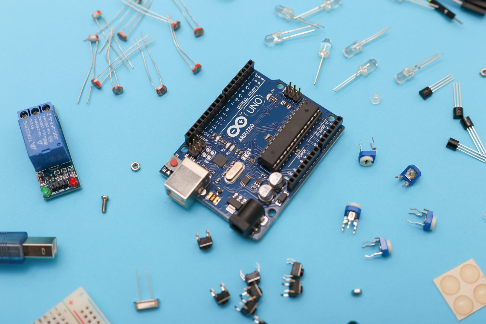
Using an LDR Sensor with Arduino: A Simple Guide to Light Detection and Device Control

Introduction
Are you curious about using an LDR (Light Dependent Resistor) sensor with Arduino? Look no further! In this guide, we will walk you through the process of setting up an LDR sensor with Arduino and controlling a device using a relay.
What is an LDR Sensor?
An LDR sensor, also known as a photoresistor, is a passive electronic component that can detect the presence or absence of light. It changes its resistance based on the amount of light falling on it. This makes it a perfect choice for various light detection and control applications.
Materials Needed
- Arduino board (e.g., Arduino Uno)
- LDR sensor
- Relay module
- Jumper wires
- Breadboard
- LED or any other device you want to control
Circuit Diagram
To get started, let’s connect the LDR sensor, Arduino, relay module, and the device you want to control according to the following circuit diagram:
Sample Code
Now that we have our circuit set up, let’s move on to the coding part. Below is a sample code that you can use to test the light detection and control functionality:
// Define the pin numbers
const int ldrPin = A0;
const int relayPin = 2;

// Define the threshold value
const int threshold = 500;

void setup() {
  // Set the relay pin as OUTPUT
  pinMode(relayPin, OUTPUT);

  // Begin serial communication
  Serial.begin(9600);
}

void loop() {
  // Read the LDR sensor value
  int ldrValue = analogRead(ldrPin);

  // Print the sensor value
  Serial.print("LDR Value: ");
  Serial.println(ldrValue);

  // Check if the light level is below the threshold
  if (ldrValue < threshold) {
    // Turn on the relay
    digitalWrite(relayPin, HIGH);
  } else {
    // Turn off the relay
    digitalWrite(relayPin, LOW);
  }

  // Delay for stability
  delay(100);
}
Explanation
Let’s go through the code step by step:
- We first define the pin numbers for the LDR sensor and the relay module.
- The threshold value is set to 500, which means that if the LDR sensor value is below 500, the light level is considered low.
- In the setup function, we set the relay pin as an output and begin serial communication for debugging purposes.
- In the loop function, we read the value from the LDR sensor using the analogRead function.
- We then print the LDR sensor value to the serial monitor.
- Based on the light level, we check if the LDR sensor value is below the threshold. If it is, we turn on the relay by setting the relay pin to HIGH. If not, we turn off the relay by setting the relay pin to LOW.
- We add a delay of 100 milliseconds to ensure stability.
Testing
Once you have uploaded the code to your Arduino board, open the serial monitor to see the LDR sensor value. Cover the LDR sensor with your hand or shine a light on it to see the changes in the sensor value. You should also observe the relay turning on and off based on the light level.
Conclusion
Using an LDR sensor with Arduino can open up a world of possibilities for light detection and control projects. Whether you want to automate your home lighting or create an interactive art installation, the combination of an LDR sensor, Arduino, and a relay module can help you achieve your goals. Have fun experimenting and exploring the endless possibilities!